

Decoding and Checking Barcode and Serial No. Areas
Overview
You can decode and check barcodes and serial numbers in areas to which a barcode inspection or serial number inspection is applied. This section describes how to configure those settings.
Assumed Operating Environment
Item Name | Product Name |
|---|---|
OS | Windows 10 |
Application | Adobe Acrobat Reader DC |
Printer driver | PS Plug-in Driver |
Image Controller | Image Controller IC-609 or Image Controller IC-607 |
Paper output options | Intelligent Quality Optimizer IQ-501 Auto Inspection Unit UK-301 Relay Unit RU-702 Video Interface Kit VI-514 Video Interface Kit VI-515 |
Setting Procedure
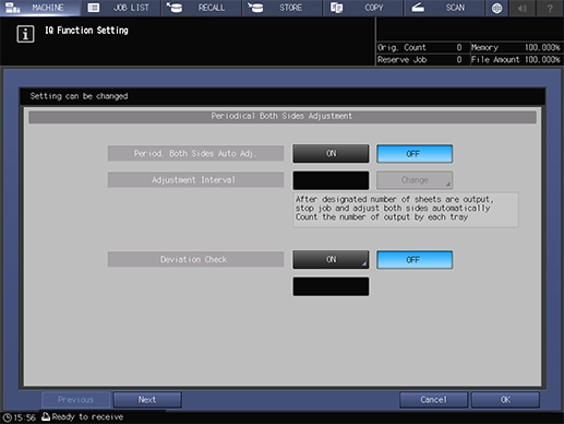
You can also configure this setting by accessing Utility/Counter, [User Setting], and then [Common Setting], or Utility/Counter, [Administrator Setting], and then [Common Setting].

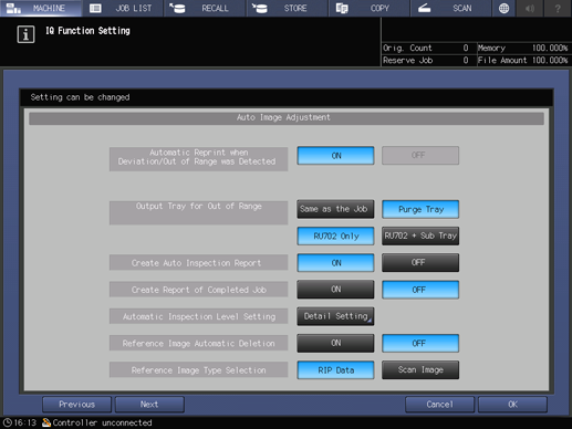

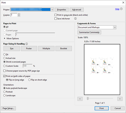
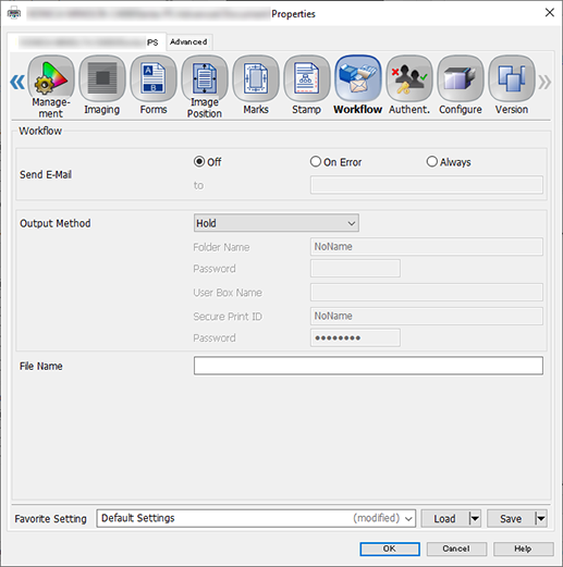
This section describes the procedure for holding a job using the PS Plug-in Driver and configuring the settings using system’s Touch panel.
When setting up the printer driver, make sure you check that none of the previous settings are left in any of the item tabs. If any of the previous settings do remain, make sure you clear them.


You can perform the same operation using AccurioPro Print Manager.
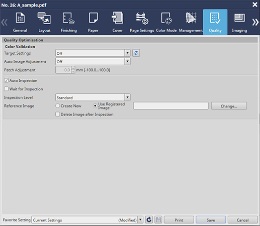

This then creates the reference image.
For example, a single reference set is selected from [Printing Pages] in the [General] tab, and printed as proof.
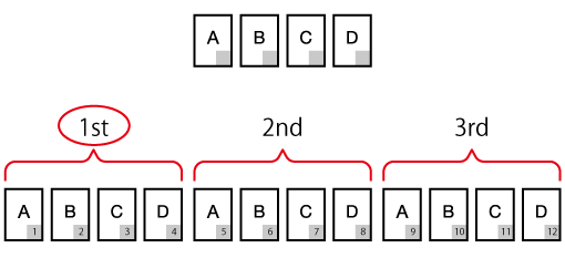
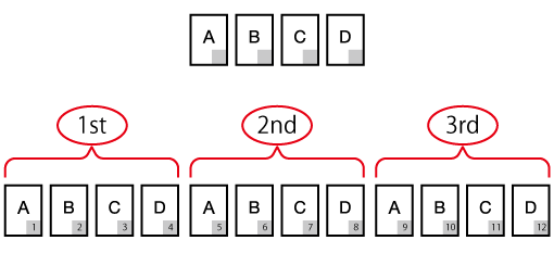
A to D: Reference images
Gray section: Variable area
The diagram shows that if there are 12 sheets in the variable job, inspection will be carried out 3 times; once for every 4 reference images (A, B, C, D). The number of inspections will be repeated depending on the number of sheets in the given job.
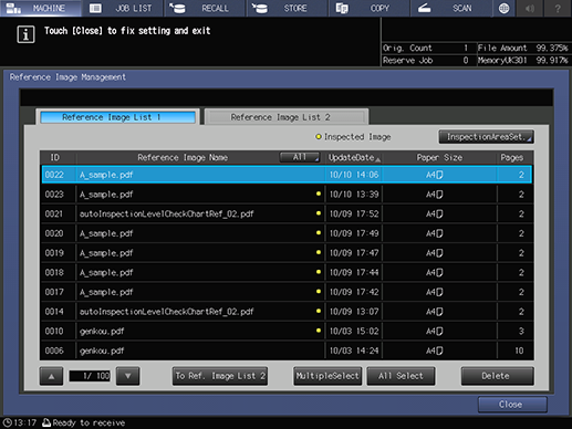
After successfully printing the proof copy, the printed data is registered as a reference image. The reference image has the same file name as the original.
The printed data is also registered and displayed as a reference image on the [MACHINE] and [Ref. Image Manage.] screens on the system’s Touch panel, as well as in [Reference Image List 1]. For details, refer to [Ref. Image Manage.] Screen.
If, after checking the contents, you want to recreate a reference image, repeat Step 1 through Step 11.
The [InspectionAreaSet.] screen is displayed.

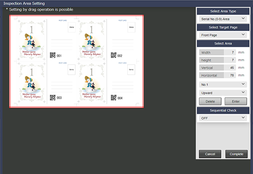
Step No. | Item | Setting Value |
|---|---|---|
1 | [Select Area Type] | For example, select [Serial No. (0-9) Area] |
2 | [Select Target Page] | Select the side to which the inspection area settings will be applied However, if you set [Select Page], you will not be able to set [Front Page] and [Back Page]. |
3 | [Select Area] | Set the area for the side selected in Step 2 Input the respective values. Alternatively, drag the mouse cursor to specify an inspection area. Press [Enter] to finish configuring the inspection area settings. |
4 | [No.1] to [No.30] | To set 2 or more [Select Area], select [No.2] (or the relevant quantity) from the menu list and repeat Step 3 You can set up to 30 for both [Front Page] and [Back Page]. If you want to delete the settings, select the number you want to delete, and press [Delete]. |

Item | Setting Value |
|---|---|
[Inspection Level] | For example, select [Standard] |
[Reference Image] | Select images with the inspection area set |
The printing begins, and the inspection area data from the print image is decoded.
In this example, the print job, including all repeat parts are printed from [Printing Pages] in the [General] tab.
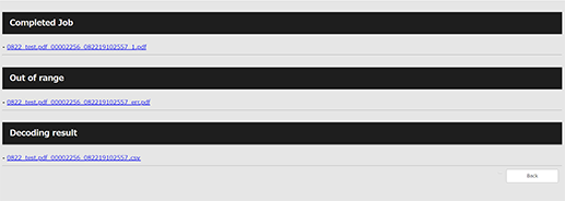
You can check the decoding results (CSV file) from the automatic inspection report.
Perform Step 1 through Step 5 from Checking Automatic Inspection Reports Using the Browser.

If the data matches, it means that the inspection area data has been printed correctly.
- For details about inspection areas, refer to [InspectionAreaSet.].

 in the upper-right of a page, it turns into
  and is registered as a bookmark.