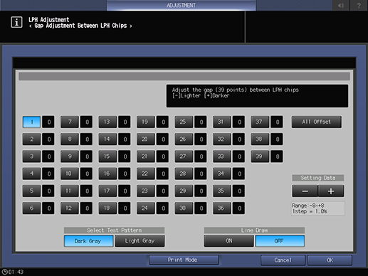
[Gap Adj. Between LPH Chips]
Overview
Correct 39 gaps between LPH chips.
Specifications
Category | Adjustment / Maintenance | ||
Location | Machine | Touch Panel | |
Printer driver | - | ||
Application | - | ||
Required items | - | ||
Setting items | Interchip gap location selection key | Select the gap location to correct. | |
[All Offset] | Corrects all locations at once. | ||
[Dark Gray] | Makes the test pattern dark gray. | ||
[Light Gray] | Makes the test pattern light gray. | ||
[ON] | Draws a line. | ||
[OFF] | Does not draw a line. | ||
[-] / [+] | Sets the adjustment value. | ||
Remarks | - | ||
Reference | - | ||
Screen access | Touch panel - [MACHINE] - [Adjustment] - [Machine Adjustment] - [LPH Adjustment] - [Gap Adj. Between LPH Chips] | ||
Procedure

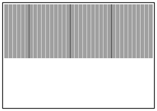
To make it easier to identify the location, select [Dark Gray] when white streaks are occurring and [Light Gray] when black streaks are occurring.

A test pattern is output.
A test pattern is output.

White lines and black lines are drawn, and each black line represents a gap of 10 units.
Check whether white and black streaks are occurring. The streaks caused by LPH is sharp. Pay attention to this sharp streak and identify the location where streaks occur.
The streaks caused by the process are wide and blurry. Do not identify such a streak as a gap location.

For white streaks, enter the numeric value in the [+] side.
For black streaks, enter the numeric value in the [-] side.
[Range:-8~+81step = 1.0%]
If the interchip correction value is too large, black streaks appear, and if it is too small, white streaks appear.
 in the upper-right of a page, it turns into
  and is registered as a bookmark.